
Motorcycle Accessory Installation Problems: Causes and Fixes
Most motorcycle accessory installation problems are best diagnosed by separating mounting security, fitment or alignment, and wiring or electrical connection. Start with the observed symptom and verify the accessory’s specified hardware, position, clearance and routing before replacing parts. If the symptom or mismatch remains after the relevant installation checks, move to compatibility or broader motorcycle diagnosis rather than forcing or over-tightening the installation.
Troubleshooting path: symptom → first check → next decision
Use the observed symptom to choose the first local installation check. These routes identify conditions to inspect; they do not prove a single cause.
Loose, shifting or rotating mount
First check Mounting stack, clamp contact, thread engagement, spacer or washer position and hardware seating.
Next decision If movement remains after the specified arrangement and tightening procedure are verified, inspect hardware fit and damage rather than adding force.
See mounting and fastener checksBolt feels tight but the bracket remains loose
First check Confirm that the fastener has not bottomed before the bracket and spacer stack are fully clamped.
Next decision Verify the specified fastener and spacing arrangement before applying any model-specific tightening requirement.
Check the mounting stackMount stays fixed but the accessory vibrates
First check Confirm the joint remains fixed, then inspect specified isolation elements, accessory support and unintended contact with nearby surfaces.
Next decision If vibration is widespread or associated with motorcycle handling, move beyond accessory-installation diagnosis.
Follow the vibration branchAccessory will not align or seat
First check Bracket orientation, loose initial assembly, hardware sequence, spacer or bushing position, clearance and interference.
Next decision A mismatch that persists after the specified parts and positions are verified requires a fitment or compatibility check; do not force the assembly.
Check alignment and fitmentElectrical accessory is intermittent or does not operate
First check With the circuit de-energised, inspect connector seating, the specified ground connection, circuit protection and wire routing.
Next decision If the recent accessory circuit checks correctly and the symptom extends beyond it, broader motorcycle electrical diagnosis is required.
Follow the wiring checksVisible fastener damage or abnormal tightening resistance
First check Fastener head, threads, receiving thread, bracket, washer or spacer and seating surface.
Next decision Stop tightening when damage is visible or cross-threading or deformation is suspected; follow the applicable hardware or repair procedure.
Inspect damaged fastenersA symptom is a route to the next check, not proof of a cause: joint movement points first to the mounting interface; poor seating points to fitment geometry; intermittent electrical operation points to the installed accessory circuit; and vibration with a fixed mount points to vibration transmission through the mounted system.
Use the applicable accessory and motorcycle instructions for model-specific hardware, torque, fuse rating, spacing and routing. Those requirements depend on the accessory and motorcycle configuration, so a universal value should not be assumed.
Table of Contents
Installation Faults Versus Accessory Fitment Problems
An installation fault means the installed accessory has been assembled, positioned or secured incorrectly, while a fitment problem remains after the intended parts, orientation and assembly sequence have been verified.
The practical distinction is whether correcting the installation condition restores the intended mounting-point alignment, hardware seating and clearance without distortion.
Model-specific brackets and hardware still need to match the motorcycle and accessory configuration before the condition can be classified confidently.
| Installation fault | Fitment mismatch |
|---|---|
| Mounting points align after the accessory and bracket are returned to the intended orientation. | Mounting points remain misaligned after the intended accessory, bracket and orientation are verified. |
| Hardware seating becomes correct after misplaced, reversed or incorrectly positioned parts are corrected. | Hardware still cannot seat as intended after the specified parts and their positions are verified. |
| Correcting the assembly sequence allows the accessory to reach its intended position. | The intended assembly sequence still leaves the accessory unable to reach its specified mounting position. |
| Required clearance is restored when the installation condition is corrected. | Interference or insufficient clearance persists with the intended parts correctly positioned. |
| The accessory reaches its intended position without forcing, distorting or modifying the intended parts. | Reaching the intended position would require forcing, distortion or modification rather than correction of the assembly. |
Mounting-point alignment, hardware seating, assembly order and clearance should therefore be checked together because the same visible misalignment can represent either an assembly error or a compatibility mismatch.
If correcting orientation, seating or sequence restores the intended mounting relationship, the condition is an installation fault; if the mismatch persists after those conditions and the model-specific parts are verified, verify accessory compatibility before changing hardware or forcing the accessory into position.
The comparison image below shows the same accessory-to-mounting-point relationship as a correctable assembly condition and as a persistent fitment mismatch.
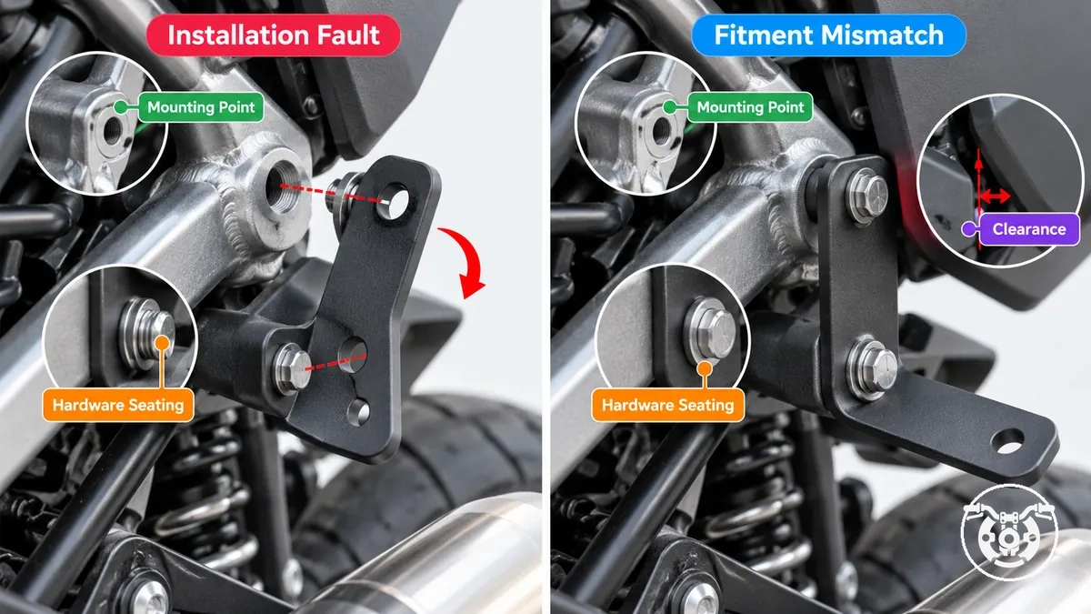
For example, a bracket in the wrong orientation may leave its mounting holes misaligned, but returning it to the intended orientation can allow the hardware to seat without distortion.
If the intended orientation, hardware and assembly sequence are confirmed yet the bracket still cannot align with the mounting points while maintaining the required clearance, treat the persistent mismatch as a fitment problem requiring a compatibility check rather than forcing the installation.
Mounting Bolt and Fastener Problems
An accessory mounting bolt can feel tight yet provide poor clamping when thread engagement, hardware seating, spacing or hardware condition prevents the bracket and mounting surface from being drawn together correctly.
Here, a mounting bolt means motorcycle accessory mounting hardware, not engine mounting hardware.
Looseness, movement or loss of retention therefore warrants inspection of the whole mounting stack: fastener, seating surface, washer or spacer where applicable, bracket and threaded attachment.
| Fastener condition | Possible symptom | Check | Corrective direction |
|---|---|---|---|
| Inadequate thread engagement | Poor clamping or loss of retention | Confirm that the specified fastener engages the intended threaded attachment correctly. | Use the specified hardware and engagement condition for the accessory and mounting point. |
| Poor seating | Bracket movement or uneven clamping | Inspect the bolt head, washer and bracket seating surface for a gap, obstruction or uneven contact. | Restore the intended seating relationship before tightening. |
| Incorrect washer or spacer arrangement | Misalignment, a remaining gap or poor clamping | Compare washer and spacer positions with the specified mounting stack and assembly order. | Return each washer or spacer to its specified position and orientation. |
| Fastener bottoms before the stack is clamped | Bolt feels tight while the bracket remains loose | Check whether the fastener has reached the end of its available threaded travel before the seating surfaces are clamped together. | Verify the specified fastener, spacer arrangement and mounting stack rather than treating resistance to further turning as proof of clamping. |
| Visible thread or fastener damage | Irregular tightening, poor retention or inability to seat correctly | Inspect the fastener and mating threads for visible deformation, stripped areas, cracks or other damage. | Do not rely on the damaged fastening condition; follow the applicable hardware or repair instructions. |
Thread engagement, seating surfaces, the washer or spacer arrangement and tightening sequence determine whether the accessory fastener can establish the intended clamping relationship.
Incorrect spacing or poor seating can leave the bracket loose even when the bolt resists further turning, while visible thread or fastener damage means the hardware condition requires assessment before the joint is relied upon.
Tightening should follow the specified requirement and sequence for the particular motorcycle accessory and mounting hardware rather than an assumed torque value.
The image below shows how the bolt, washer or spacer, bracket, seating surface and thread-engagement area form the mounting stack that produces clamping.
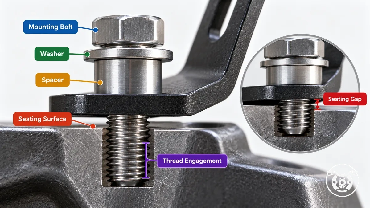
For example, if an accessory mounting bolt reaches the end of its available threaded travel before the bracket and spacer stack is fully clamped, the bolt can feel tight while a gap and movement remain at the seating surface.
In that condition, verify the specified bolt and spacing arrangement first, then use the tightening requirement stated in the applicable accessory or motorcycle instructions rather than applying an assumed torque.
Fasteners That Loosen or Will Not Hold
Fastener loosening that returns after tightening points to a retention or seating problem that should be identified rather than simply applying more force.
Check the retention path in this order
- Thread engagement: confirm that the specified fastener engages the intended threaded attachment correctly.
- Seating and clamping contact: verify that the bracket, washer or spacer and mounting surface make the intended contact without a gap or obstruction.
- Hardware match: compare the fastener and washer or spacer arrangement with the specified mounting stack.
- Damage: if loosening returns after correct assembly and the specified tightening procedure, inspect the fastener and mating threads for damage.
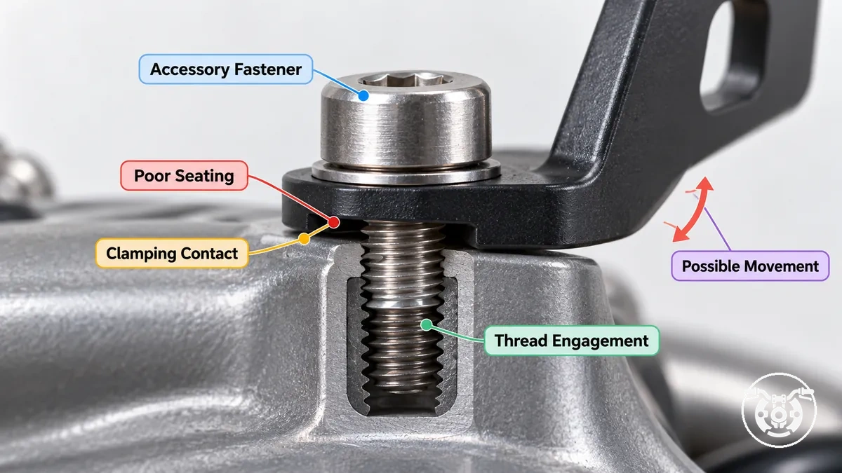
The image illustrates why apparent tightness does not by itself establish secure clamping: the fastener needs the intended thread engagement while the clamped parts make the intended seating contact.
If those conditions are correct but movement continues after the specified tightening procedure, check that the hardware specification matches the mounting arrangement and inspect the fastener and mating threads for thread damage rather than assuming that further tightening will restore retention.
Over-Tightened, Stripped or Damaged Fasteners
Over-tightening or thread damage can make an accessory mounting interface less reliable rather than improve clamping.
Excessive tightening can damage the fastener or receiving thread, while cross-threading or a stripped thread can compromise thread engagement and make later tightening unreliable.
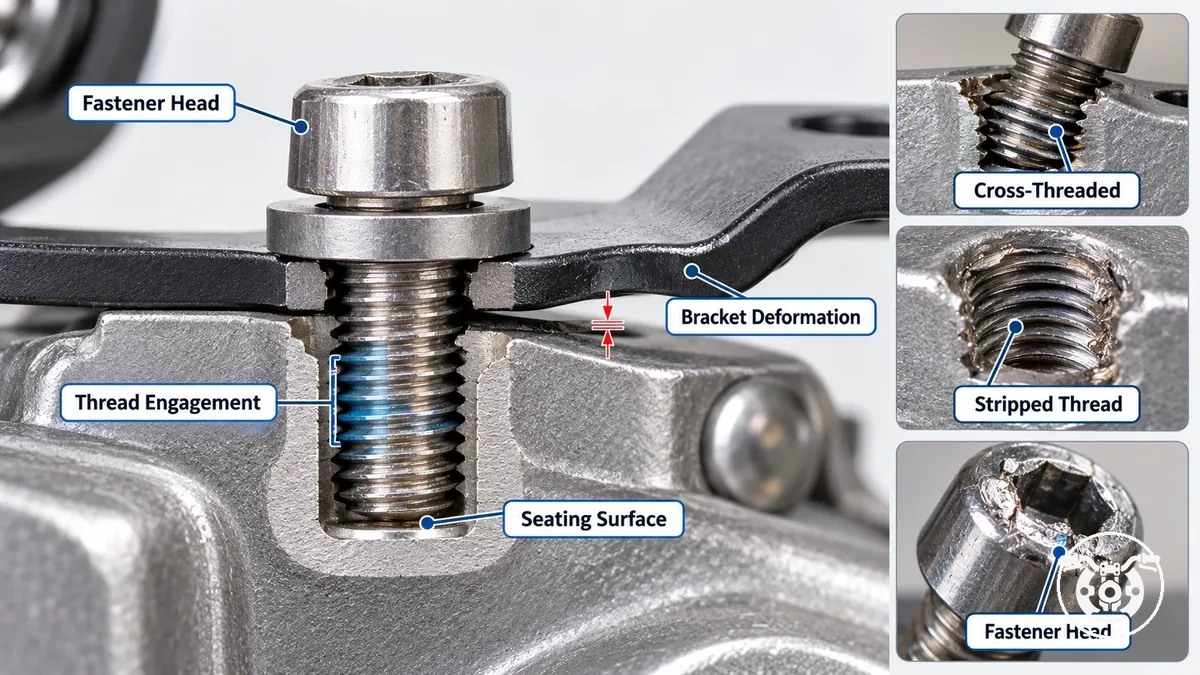
Stop and assess the mounting interface when you find:
- Cross-threading or stripped threads that compromise normal thread engagement.
- A damaged fastener head that prevents controlled tightening.
- Deformed bracket, washer or spacer surfaces that prevent the mounting stack from seating as intended.
- Abnormal resistance during tightening that suggests cross-threading or deformation rather than normal clamping.
Mounts That Shift, Rotate or Vibrate After Installation
An accessory mount that shifts or rotates has movement at the clamp or joint, while a secure mount can remain fixed and still transmit vibration to the attached accessory.
The first diagnostic branch is therefore physical joint movement versus vibration with no movement at the mounting interface.
During a safe static check, observe the accessory mount against a fixed reference point to determine whether the joint itself moves.
The image below distinguishes a slipped or rotated joint from a secure mount that remains fixed while vibration is visible at the attached accessory.
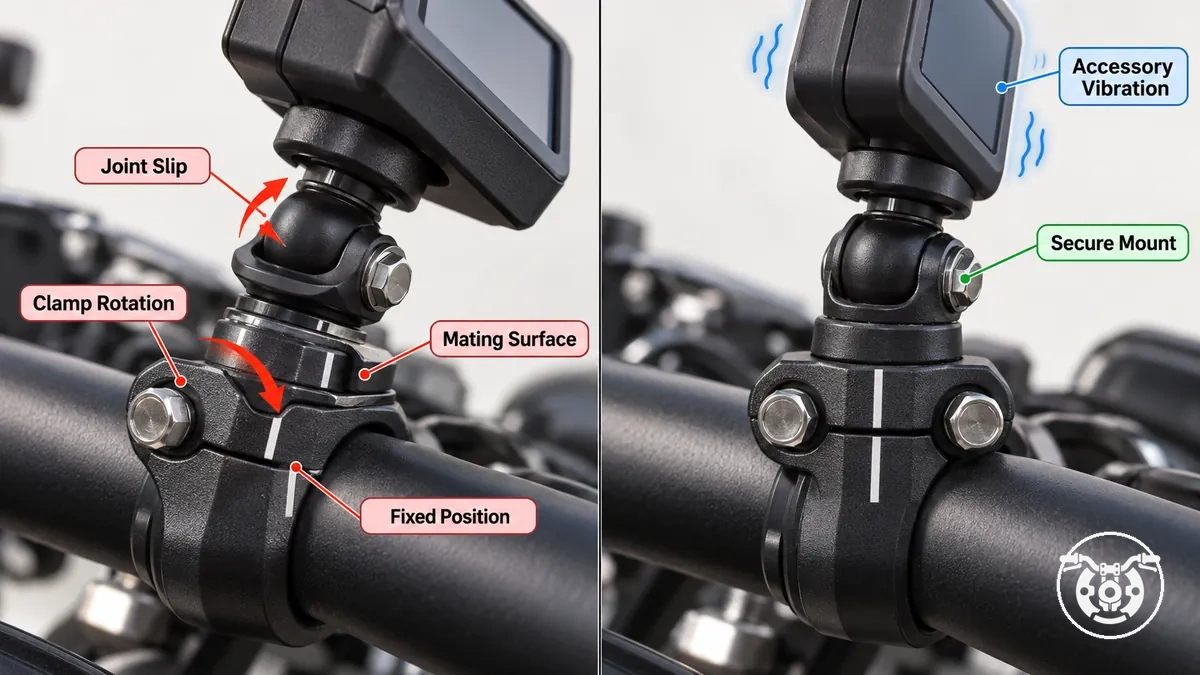
| Observed symptom | Likely local condition | Check | Corrective direction |
|---|---|---|---|
| Accessory mount shifts at the joint | Clamp grip or joint preload may be insufficient at the mounting interface. | Check whether the clamp and joint move relative to the fixed mounting point. | Verify the specified mounting arrangement, hardware seating and tightening requirements. |
| Clamp or accessory mount rotates | Mating-surface contact or hardware seating may be incomplete or incorrectly positioned. | Inspect the mating surface, clamp position and hardware seating for the intended contact. | Restore the specified seating and contact condition before relying on the joint. |
| Mount has uneven or incomplete contact | A gap, incorrect spacing or uneven mating-surface contact may reduce clamp grip. | Inspect the hardware stack and mating surface for gaps, interference or uneven seating. | Correct the local seating or spacing condition according to the applicable mounting instructions. |
| Mount stays fixed but accessory vibrates | Vibration is transmitted through the secure mount; accessory mass, leverage or the condition of specified vibration-isolating elements may influence the accessory's motion. | Confirm that the joint remains fixed, then inspect the accessory support and any specified isolation elements. | Keep the diagnosis on the accessory mounting system and verify its specified support and isolation arrangement. |
If the joint moves, inspect clamp grip, mating-surface contact, joint preload and hardware seating because a deficiency at one of these local interfaces can correspond to slipping or rotation.
Greater accessory mass or leverage increases the load applied through the mounting interface, so the specified support arrangement matters when movement occurs.
Where vibration-isolating elements are part of the accessory mount, inspect their seating, condition and specified arrangement; if the joint remains fixed, follow the secure-mount vibration branch rather than assuming that additional clamp force is appropriate.
For example, if an accessory changes position relative to a fixed reference point during a safe static check, the accessory mount or joint is moving, so its local grip, contact and seating conditions require inspection.
If the secure mount remains fixed while only the attached accessory visibly shakes, treat the symptom as transmitted vibration through the fixed mounting interface; a widespread or handling-related symptom falls outside this accessory-installation diagnosis.
Clamps or Joints That Slip Despite Tight Fasteners
A clamp or articulated joint can slip even when its fastener feels tight if the interface does not create the contact and grip needed to resist movement.
Fastener resistance to further turning is not the same condition as secure clamping; the clamp or joint still needs its intended interface fit and contact surface engagement to create grip.
At an accessory mount, the local diagnostic focus is therefore the fit and contact relationship between the joint faces rather than fastener tightness alone.
The image below shows how contact area, spacer position and fastener bottoming can allow slipping even when the fastener feels tight.
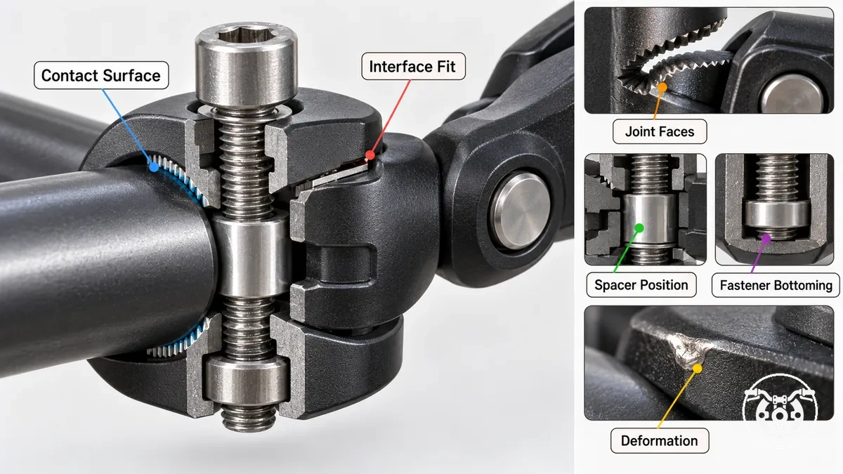
- Interface contact
- The clamp halves or joint faces need their intended fit and contact; joint teeth or a friction face, where present, should engage in the intended position.
- Spacer or insert position
- A misplaced spacer or insert can change the contact relationship and reduce grip even when the fastener feels tight.
- Fastener travel
- Fastener bottoming can create resistance to further turning before the mating surfaces establish the intended clamping contact.
- Surface condition
- Visible deformation of the clamp, joint face, spacer or surrounding contact surface can prevent correct seating.
Correct the identified fit, contact, spacer, bottoming or deformation condition according to the applicable mounting instructions rather than treating more tightening as the default response.
Accessory Vibration That Persists With a Secure Mount
Accessory vibration can persist even when a secure mount remains fixed because vibration transmission can reach the attached accessory without the mounting joint slipping.
Confirm that the mount stays in the same position relative to its mounting point while the accessory shakes; this observed condition keeps the local diagnosis on vibration passing through or around the fixed mounting interface.
Isolation element
Inspect any specified pad or damper for correct position, seating and intact condition; a misplaced, worn or damaged element can change vibration transmission.
Unintended contact
Check whether the accessory touches an adjacent surface that can provide another vibration path while the mounting joint itself remains fixed.
Position or load effect
If vibration changes with accessory position or load, treat that as a clue that the installed support condition influences the shake, not as proof that extra damping is required.
Accessories That Do Not Align or Seat Correctly
If an accessory does not align or seat correctly at its intended mounting point, check bracket orientation, hardware sequence, spacer or bushing position, clearance and interference before applying force or considering modification.
Work through the mounting geometry before applying force
- Bracket orientation: confirm that the accessory approaches each mounting point in the specified orientation.
- Loose initial assembly: keep the relevant fasteners loose enough for the parts to settle into their intended positions before final tightening.
- Hardware sequence and spacing: verify the order and position of every washer, spacer or bushing because an incorrect stack can shift alignment and clearance.
- Clearance and interference: check for another installed part or obstruction that prevents the accessory from sitting squarely or flush.
Alignment returns after correction
If the specified orientation, hardware order, spacing and clearance let the mounting points align without drawing the parts together by force, the mismatch is consistent with a correctable assembly error.
Mismatch persists after verification
If the accessory still cannot sit squarely or align after those conditions are verified, treat it as a fitment or compatibility problem and do not force the assembly.
Verify the intended accessory application and mounting requirements before proceeding with any permanent modification.
Mounting Points That Will Not Line Up
If an accessory mounting hole or bracket will not line up with its intended mounting point, verify orientation, loose initial assembly, spacer position and any local obstruction before applying force.
A reversed or incorrectly positioned bracket can place the mounting hole outside its intended alignment, while tightening one fastener too early can constrain the movement available for the remaining mounting points to align.
A spacer in the wrong location can shift the bracket geometry, while an obstruction or interference can prevent the accessory from reaching its intended position.
Keep the fasteners in the intended loose initial assembly state while checking these local mounting conditions.
Narrow the mismatch by confirming bracket orientation first, then the mounting order and spacer location, and finally whether an obstruction or interference prevents the mounting hole from reaching the intended mounting point.
If correcting one of these conditions allows the mounting points to line up during loose initial assembly, the mismatch is consistent with a local assembly error.
If a persistent mismatch remains after the specified orientation and intended loose initial assembly have been verified and no local obstruction explains the offset, verify the accessory's compatibility and mounting requirements rather than forcing the parts together.
Incorrect Assembly Order or Spacer Placement
Incorrect assembly order or spacer placement can change the final geometry of an accessory mounting stack, affecting clearance, alignment and clamping even when the individual parts are otherwise suitable for the mounting point.
The position of a spacer, washer or bushing within the bracket stack can change the resulting gap or bracket position, while fastener order can constrain how the parts settle before clamping is established.
A stack that differs from the intended arrangement can therefore leave the accessory offset, inadequately seated or clamped in a different relationship than intended.
The exact bracket stacking and fastener insertion order is accessory-specific and should be verified against the applicable accessory or motorcycle instructions.
Accessory Wiring Problems After Installation
If accessory wiring develops a fault during or after installation, check the recently installed accessory circuit first: connector seating, the ground electrical connection, applicable circuit protection and wire routing should be verified before a motorcycle-wide electrical fault is assumed.
These checks separate observable installation conditions from faults that would require broader electrical diagnosis.
The table below connects common accessory symptoms with local installation conditions and safe checks without treating any one condition as the confirmed cause.
| Accessory symptom | Likely installation condition | Safe check | What the result suggests |
|---|---|---|---|
| Accessory is intermittent or cuts out | Connector may be incompletely seated or an electrical connection may be loose. | With the circuit de-energised, inspect the connector for its intended seating and secure engagement. | A connector that is not fully seated identifies a local connection condition to correct according to the applicable installation instructions. |
| Accessory does not operate after installation | Ground connection may be incomplete, loose or incorrectly positioned. | With the circuit de-energised, inspect the installed ground point and connection against the specified arrangement. | An incorrectly seated or positioned ground identifies a local electrical connection condition to correct and retest before expanding the diagnosis. |
| Accessory circuit stops operating | Circuit protection may have opened where a fuse or other protective device is specified. | Check the specified protective device and its condition using the accessory and motorcycle instructions. | An open protective device requires the underlying accessory-circuit condition to be identified; do not bypass the protection or substitute an unsupported rating. |
| Operation changes with movement | Wire strain, a pinch point or damaged insulation may be affecting the routed wire. | Inspect routing where the wire passes near moving parts and where steering or suspension movement changes its position. | Visible strain, pinching or insulation damage identifies a routing condition to correct using the specified cable path and protection. |
Connector seating and ground condition should match the specified electrical connection arrangement, while circuit protection must retain the type and rating specified for that accessory circuit rather than an assumed universal value.
Inspect routing for wire strain, pinch points and visible insulation damage, particularly where normal steering or suspension movement changes the wire's position.
These observations narrow the diagnosis to installation conditions without assigning a cause until the relevant connection, protection or routing check supports it.
For example, if an intermittent accessory cuts out only as its routed wire moves near a steering or suspension area, inspect that local route for strain, pinching, connector movement or insulation damage rather than assuming the movement itself proves a specific electrical fault.
If the recent accessory connections and routing check correctly and the electrical symptom extends beyond the installed accessory circuit, broader motorcycle electrical diagnosis falls outside this installation-focused check.
Poor Grounds or Loose Electrical Connections
A poor ground or loose connector can correspond to intermittent operation, weak operation or complete loss of accessory function, but the symptom alone does not establish either condition as the cause.
- Connector seating
- Confirm complete connector engagement; incomplete seating can interrupt the intended electrical connection.
- Terminal retention
- Check that each terminal remains securely retained in the connector rather than moving out of position.
- Ground attachment
- Verify the specified attachment position and inspect the contact for visible looseness, corrosion or damage.
If accessory operation cuts out as a connector or ground attachment moves, inspect that connection for incomplete engagement, weak terminal retention or a visibly insecure contact condition; movement-related intermittent operation makes that local connection relevant to the diagnosis but does not by itself prove the cause.
Visible corrosion or damage at a terminal or ground contact also identifies a condition requiring correction according to the applicable accessory or motorcycle instructions before the connection is retested.
If the connector, terminals and ground attachment remain correctly seated and secure after these checks, the symptom requires diagnosis beyond these local connection conditions rather than replacement of wider motorcycle wiring based on the accessory symptom alone.
Pinched, Tight or Poorly Routed Wiring
A pinched wire, stretched cable or poor wiring route can create wire strain, damage insulation, load a connector or restrict normal movement, and these conditions can correspond to intermittent accessory operation.
Verify the whole cable path
- Pinch and tension: the route should not trap the wire or place excessive strain on the cable or connector.
- Support: clips or ties should support the cable without creating a pinch point or concentrating pressure.
- Heat, edges and abrasion: maintain the clearance required by the applicable instructions and inspect insulation where the cable passes near hot, sharp or abrasive surfaces.
- Movement allowance: through the relevant steering or suspension travel, the cable should not become taut, trapped or load the connector.
If accessory operation changes as the handlebars or suspension move, treat that change as a diagnostic clue to inspect the corresponding path for a pinched wire, wire strain or connector strain rather than proof of a specific fault.
The required clearance, practical bend radius and movement allowance depend on the accessory, motorcycle and specified wiring route, so use the applicable installation instructions rather than a universal dimension.
Verifying a Secure Installation After Troubleshooting
Verifying a secure installation after troubleshooting means confirming that the corrected accessory retains its intended position, has the required clearance from controls and moving parts, and no longer shows the original symptom during an appropriate functional check.
Where the accessory has electrical connections, wiring routing and connection integrity should also match the applicable installation requirements.
Exact acceptance criteria depend on the accessory design, motorcycle configuration and applicable instructions rather than a universal threshold.
- Retention: Verify that the accessory remains secure at its mounting points; unresolved movement means the installation has not passed the check.
- Position: Confirm that the accessory remains in its intended alignment or position; an offset or displaced component requires correction before normal use.
- Clearance: Check that the installed accessory does not interfere with controls or moving parts through the movement relevant to its mounting location; any interference is a stop-use condition.
- Fastener condition: Inspect the mounting hardware for correct seating and visible damage; damaged or improperly seated hardware requires correction according to the applicable instructions.
- Wiring routing: Where wiring or cables are present, verify that their routing remains supported and does not become trapped, taut or interfere with normal movement.
- Connection integrity: Where applicable, confirm that electrical connections remain correctly seated and that the accessory does not reproduce an unresolved electrical symptom.
- Functional check: Perform the static or other low-risk functional check appropriate to the accessory and confirm that the original symptom does not return; recurrence means troubleshooting is not complete.
A successful check supports resuming use only for the conditions examined; it does not guarantee that the installation will remain secure indefinitely.
When any acceptance criterion is not met, return to the applicable motorcycle accessory installation procedure and resolve the condition before normal use resumes.